





| Place of Origin: | China |
|---|---|
| Brand Name: | TMTECK |
| Certification: | CE |
| Model Number: | TM260 |
| Minimum Order Quantity: | 1 |
| Price: | Negotiation |
| Packaging Details: | Carton |
| Delivery Time: | 5-8 work days |
| Payment Terms: | T/T,PayPal |
| Supply Ability: | 50 pieces within one week |
| Standards: | DIN,ISO,ASTM,BS | Calibration: | Zero And Foil Calibration |
|---|---|---|---|
| Interface: | USB2.0 | Data memory: | 500 Readings |
| Warranty: | 2 Years | Service: | OEM, OBM. ODM |
| Highlight: | 500 Readings Data Memory Coating Thickness Gauge,USB2.0 Interface Paint Thickness Meter,DIN ISO ASTM BS Standards Coating Thickness Gauge |
||
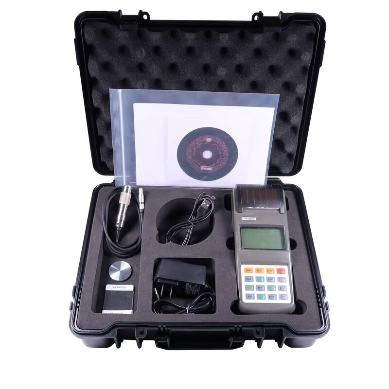
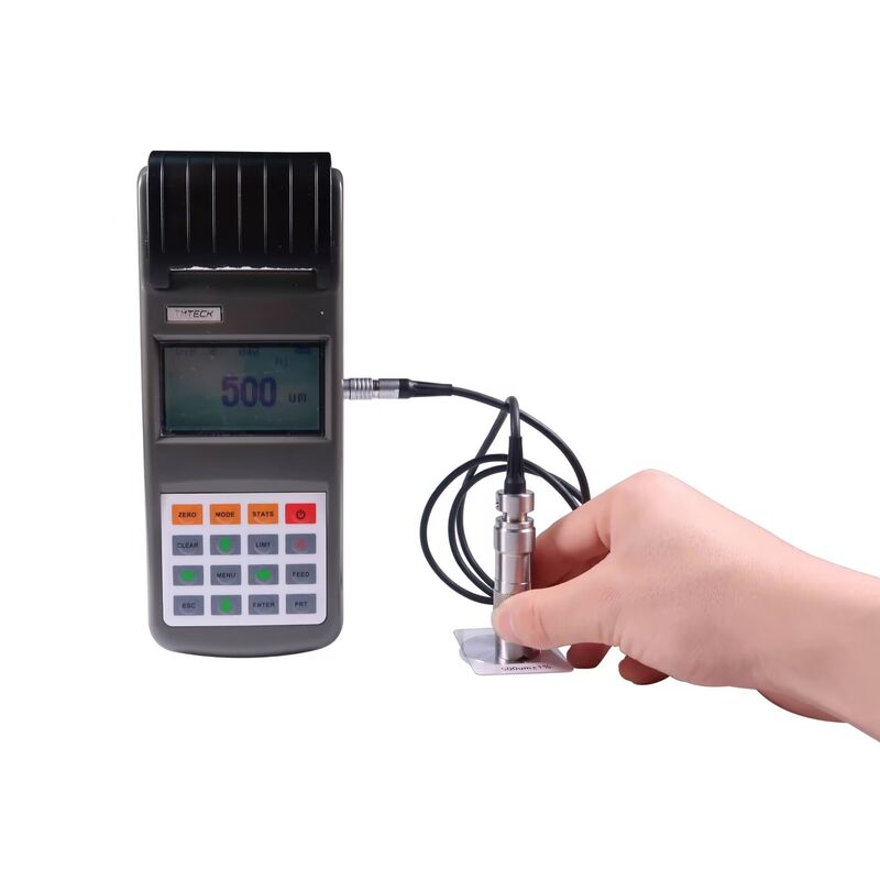
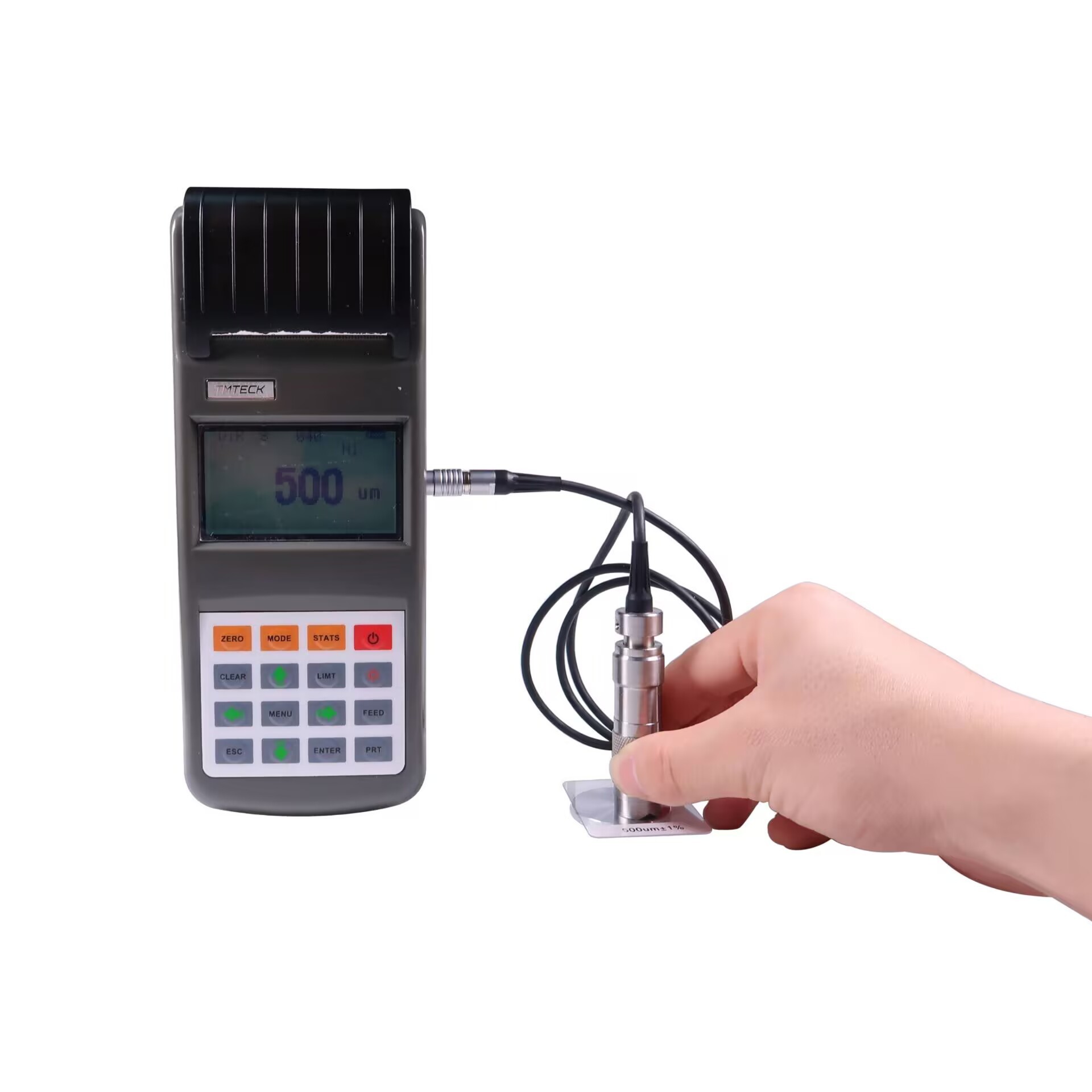
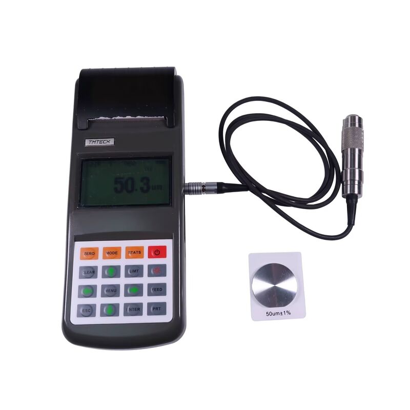
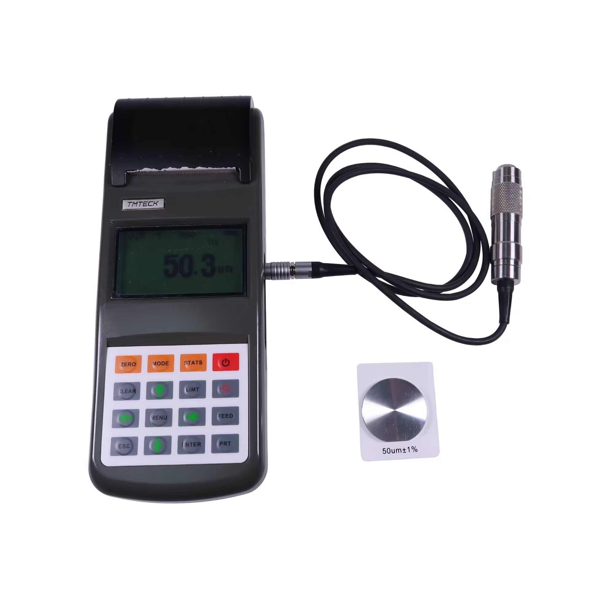
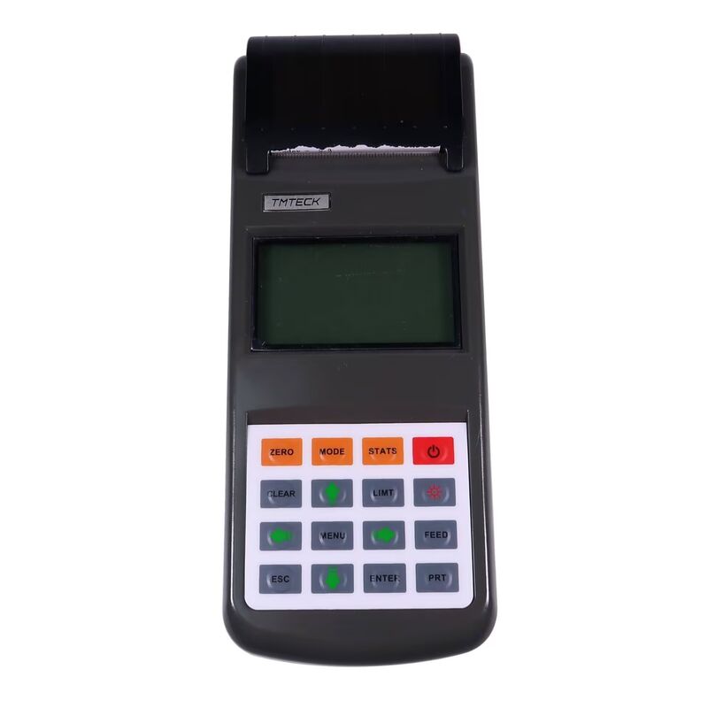
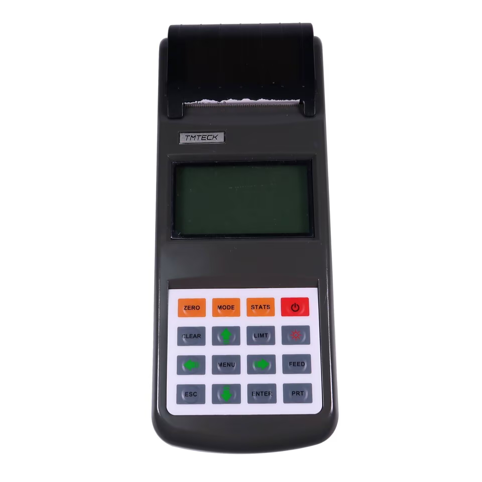
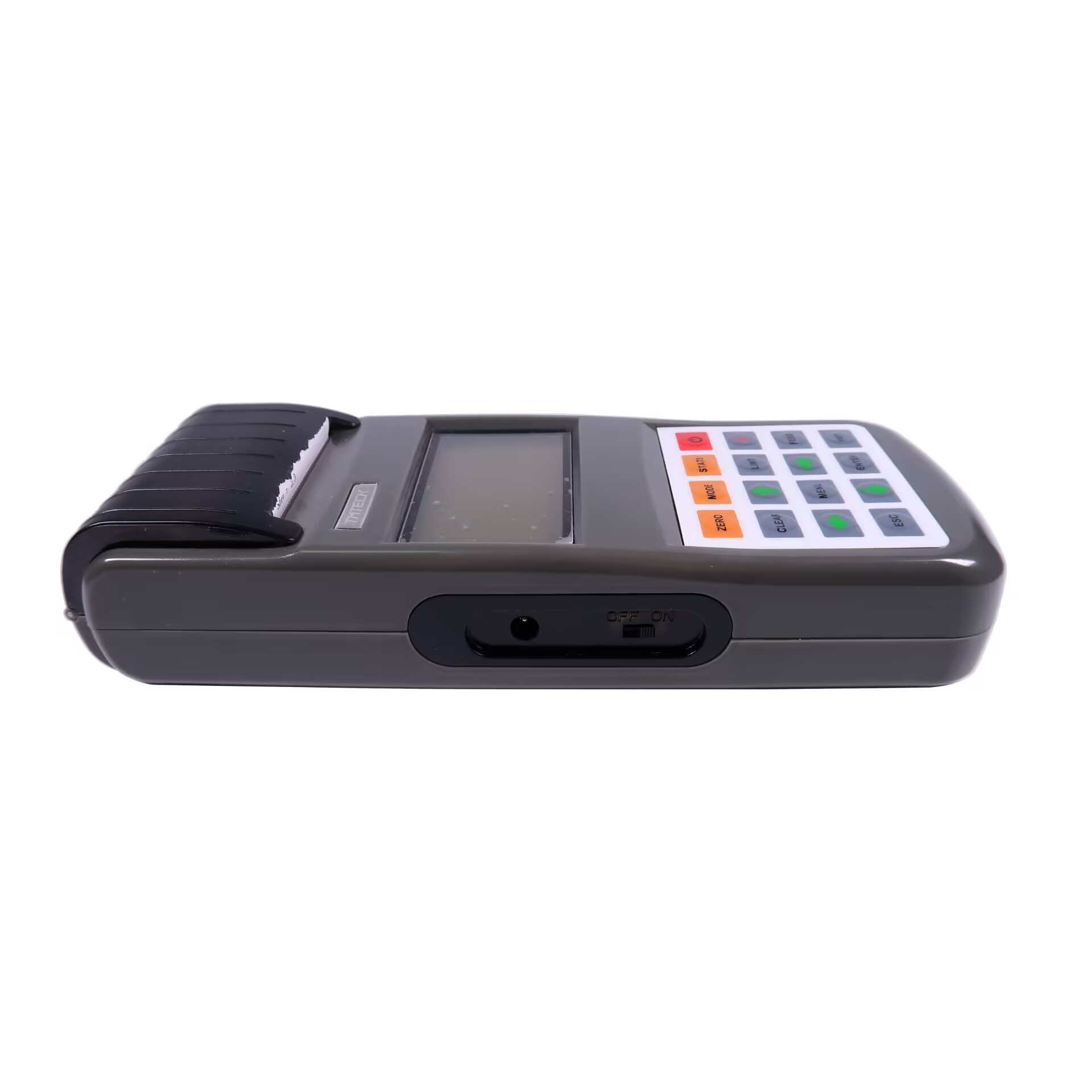
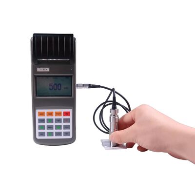
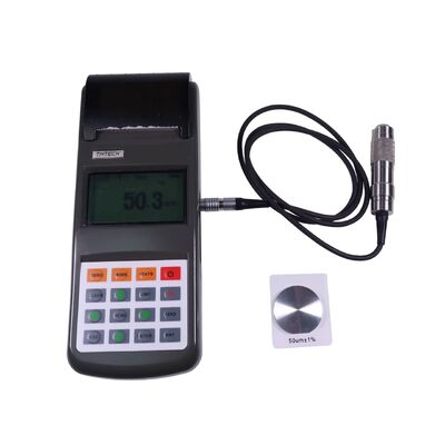
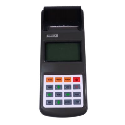
The TM260 Portable Digital Coating Thickness Gauge employs two measurement principles: magnetic induction for ferrous substrates and eddy current for non-ferrous substrates. It delivers fast, non-destructive, and precise measurement of non-magnetic coating thickness on magnetic metal substrates, as well as non-conductive coating thickness on non-magnetic metal substrates. The instrument supports six optional probes for varied applications and is equally suited to field testing and laboratory research.
| Probe types | F | N |
| Measuring methods | Magnetic induction | Eddy current |
| Measuring range | 0 ~ 1250 μm | 0 ~ 1250 μm; 0 to 40 μm (for chrome plate on copper) |
| Minimum resolution | 0.1 μm | |
| Tolerance — zero point calibration | ±(3%H+1) μm | ±(3%H+1.5) μm |
| Tolerance — two-point calibration | ±[(1~3)%H+1] μm | ±[(1~3)%H+1.5] μm |
| Measuring condition — min. curvature radius (mm) | Convexity 1.5 | Convexity 3 |
| Measuring condition — min. testing area diameter (mm) | Ø7 | Ø5 |
| Measuring condition — critical thickness of substrate (mm) | 0.5 | 0.3 |
| Standards | DIN, ISO, ASTM, BS | |
| Calibration | Zero and foil calibration | |
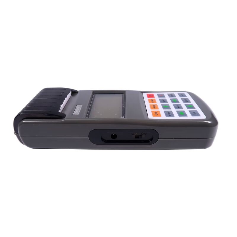
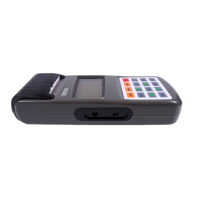
| Interface | USB 2.0 | |
| Statistics | Number of measurements, mean, standard deviation, maximum, and minimum | |
| Data memory | 500 readings | |
| Limits | Adjustable with alarm | |
| Power | Li rechargeable battery | |
| Operating environment | Temperature: 0~40 ℃; Humidity: 20%~90%; no strong magnetic field | |
| Dimensions (mm) | 215 * 84 * 42 | |
H denotes the thickness of the tested piece.
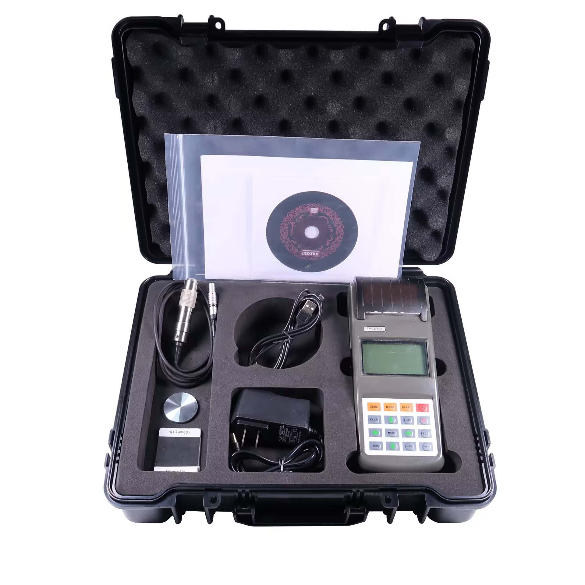
| Item | Quantity |
|---|---|
| Main unit | 1 |
| Probe | 1 |
| Substrate | 1 |
| Calibration foil | 1 |
| Charger | 1 |
| Printing paper | 1 |
| Certificate | 1 |
| Warranty card | 1 |
| Instruction manual | 1 |
| Probe model | F400 | F1 | F1/90º | F10 | N1 | F5 |
|---|---|---|---|---|---|---|
| Operating principle | Magnetic induction | Eddy current | ||||
| Measuring range (μm) | 0–400 | 0–1250 | 0–1250 | 0–10000 | 0 to 1250 μm; 0 to 40 μm (for chrome plate on copper) | 0–1250 |
| Low range resolution (μm) | 0.1 | 0.1 | 0.1 | 10 | 0.1 | 0.1 |
| Accuracy — one-point calibration (μm) | ±(3%H+1) | ±(3%H+1) | ±(3%H+1) | ±(3%H+10) | ±(3%H+1.5) | ±(3%H+1) |
| Accuracy — two-point calibration (μm) | ±[(1~3)H%+0.7] | ±[(1~3)H%+1] | ±[(1~3)H%+1] | ±[(1~3)%H+10] | ±[(1~3)%H+1.5] | — |
| Measuring conditions — min. curvature of the min. area (mm) | Convex 1 | Convex 1.5 | Convex 1.5 | Flatten 10 | Convex 3 | Angle |
| Measuring conditions — diameter of the min. area (mm) | φ3 | φ7 | φ7 | φ40 | φ5 | φ7 |
| Measuring conditions — critical thickness of substrate (mm) | 0.2 | 0.5 | 0.5 | 2 | 0.3 | 0.5 |
H denotes the thickness of the tested piece.