





| Place of Origin: | China |
|---|---|
| Brand Name: | TMTECK |
| Certification: | CE |
| Model Number: | TM520FN PLUS |
| Minimum Order Quantity: | 1 |
| Price: | Negotiation |
| Packaging Details: | Carton |
| Delivery Time: | 5-8 work days |
| Payment Terms: | T/T |
| Supply Ability: | 50 pieces within one week |
| Measuring Range: | 0-1250µ With Standard Probe F1.N1 (10.000mm Max) | Standards: | DIN, ISO, ASTM,BS |
|---|---|---|---|
| Calibration: | Zero And Foil Calibration | Data Memory: | 500 Measuring Data |
| Warranty: | 2 Years | Service: | OEB, ODM, OBM |
| Highlight: | High Temperature Coating Thickness Gauge,500 Data Memory Coating Thickness Meter,USB 2.0 Coating Thickness Gauge |
||
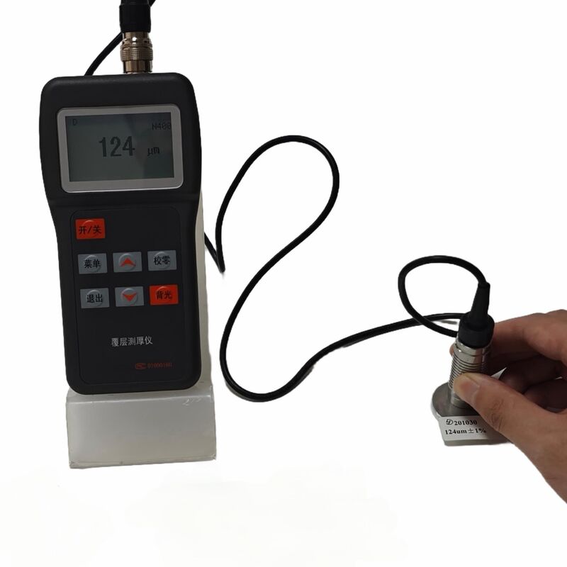
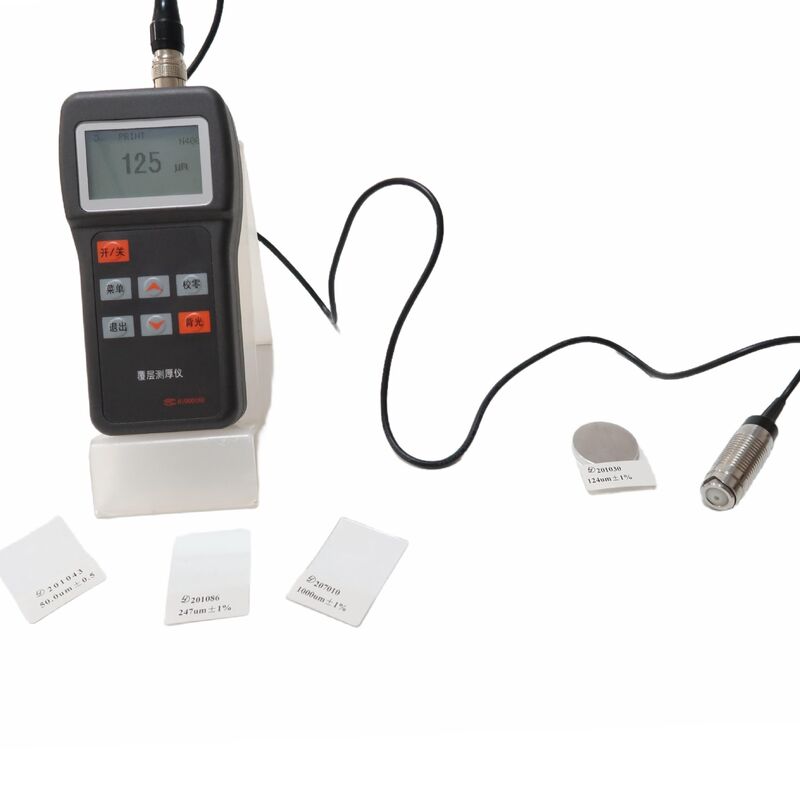
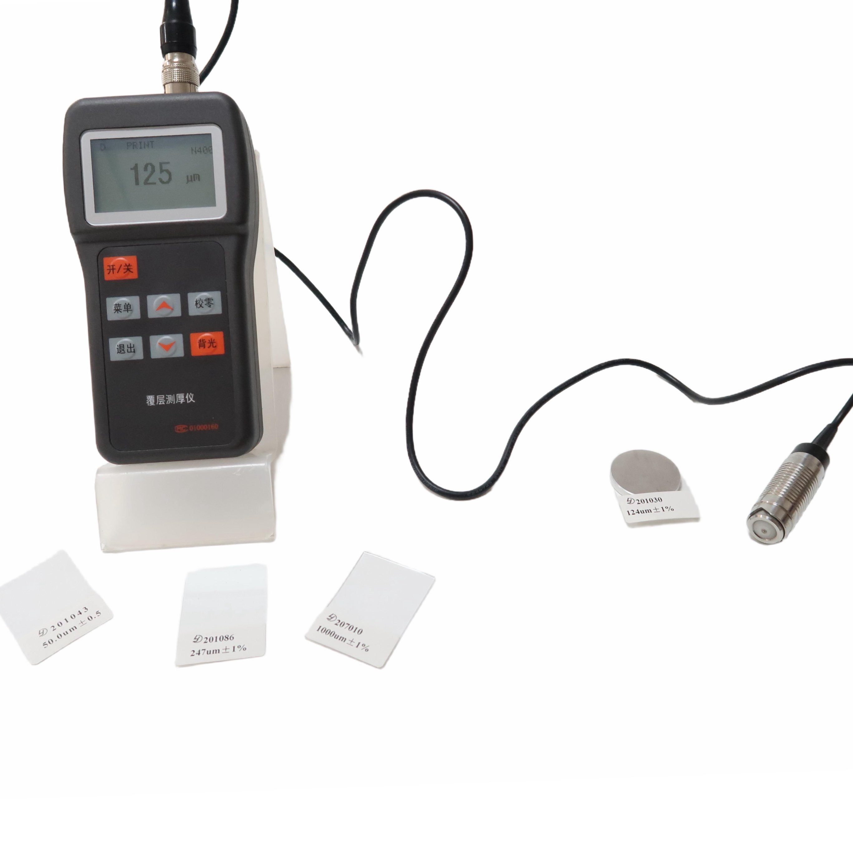
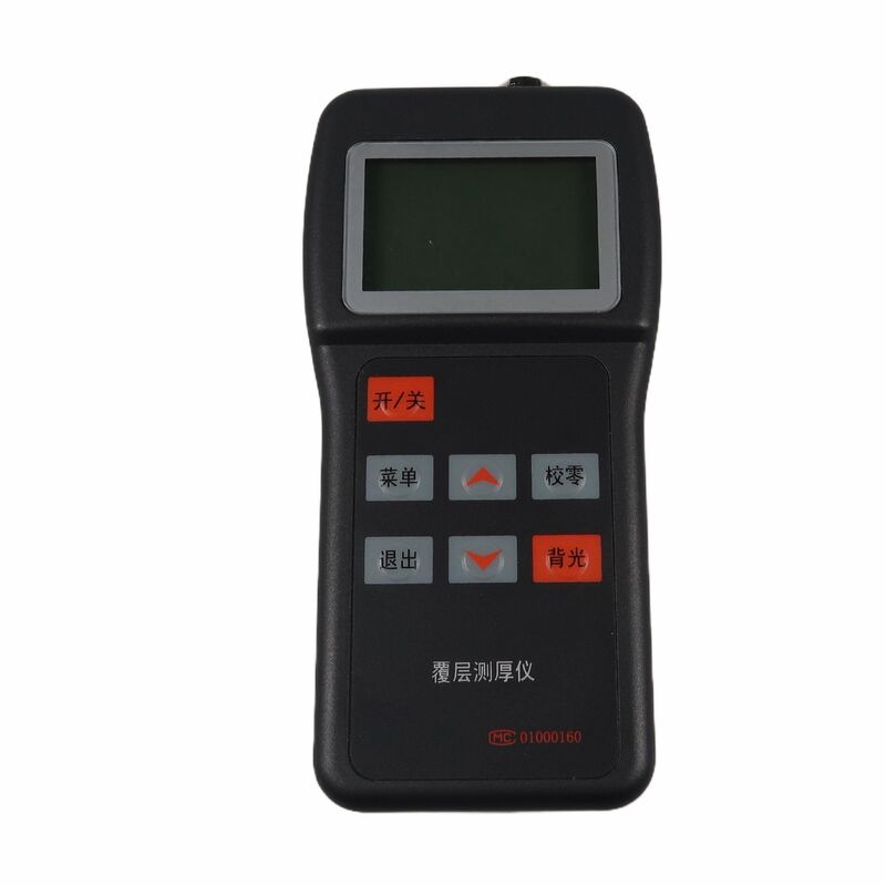
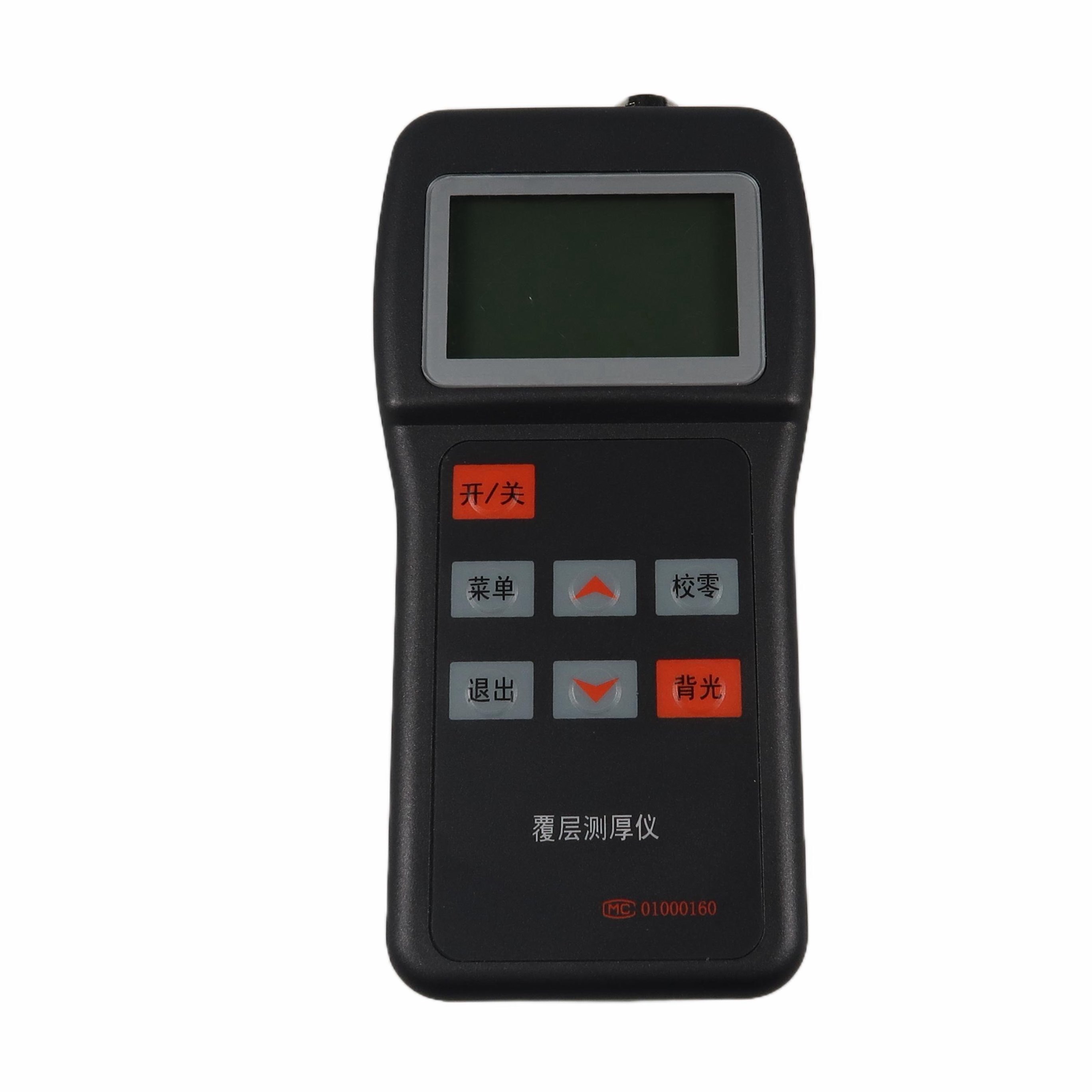
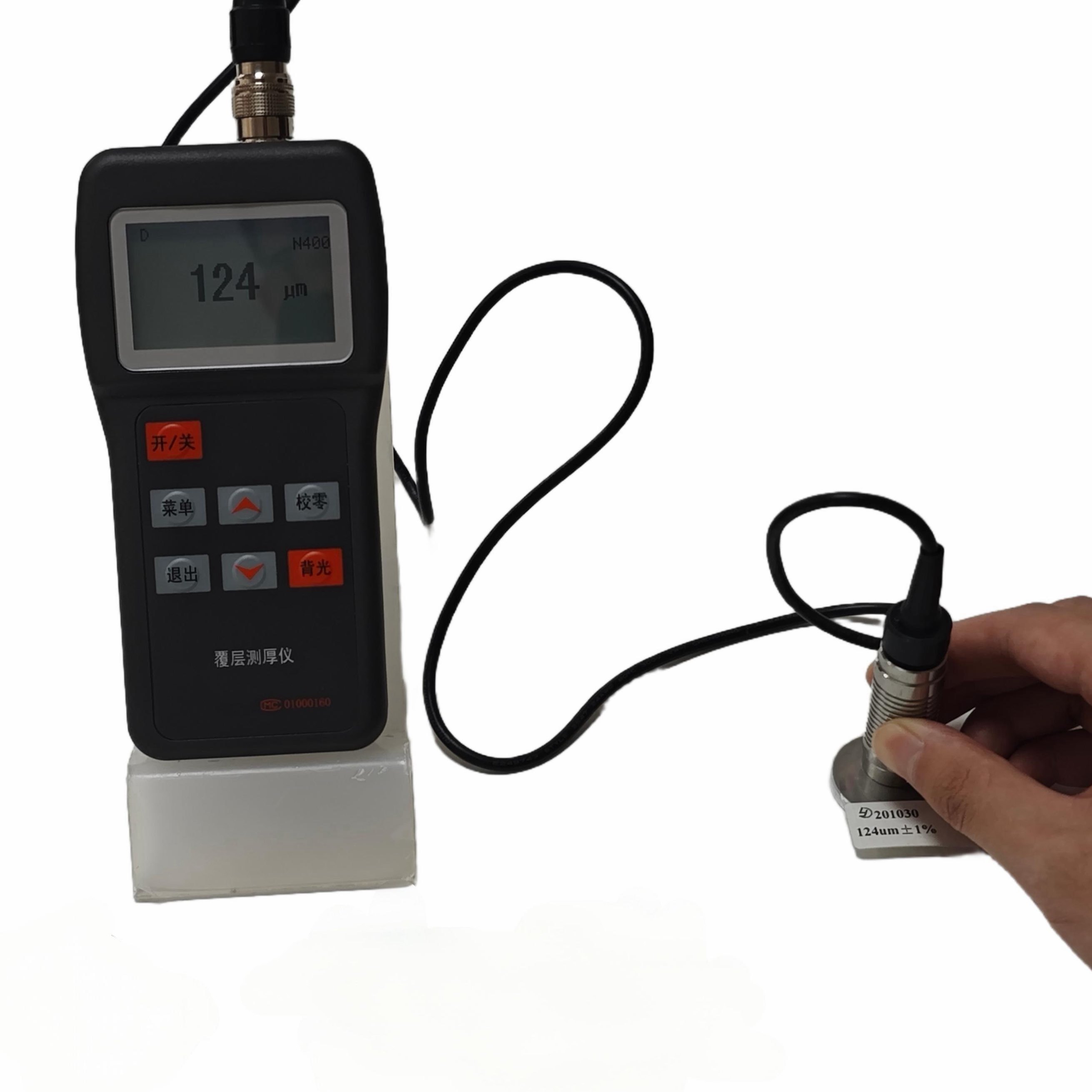
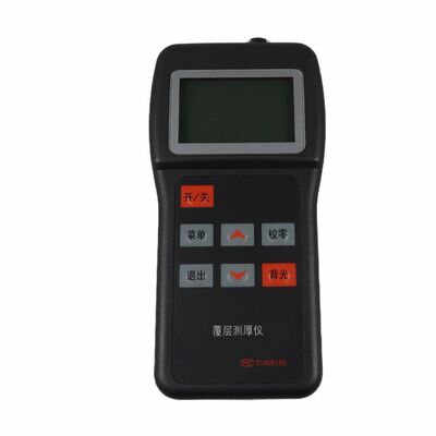
The TM520FN PLUS is a high-temperature coating thickness gauge engineered for precise, non-destructive measurement of coatings on both ferrous and non-ferrous metal substrates. Supplied with a dedicated F300 probe, it is capable of measuring on surfaces with temperatures reaching up to 300 °C.
| Measuring range | 0–1250 µm with standard probe F1 / N1 (10.000 mm max) |
| Probes available | 5 probes available for F (ferrous: on steel/iron) and N (non-ferrous metals) |
| Tolerance | F1: ±(1 µm + 3%H); N1: ±(1.5 µm + 3%H) — H: actual thickness tested |
| Resolution | Alphanumeric with 4 large digits |
| Operation language | English |
| Standards | DIN, ISO, ASTM, BS |
| Min. measuring area | F1 (standard probe) |
| Min. curvature radius | Convex: 3 mm; concave: 50 mm |
| Min. substrate thickness | Type F: 0.5 mm; type N: 50 mm |
| Calibration | Zero and foil calibration |
| Statistics | Number of measurements, mean, standard deviation, maximum and minimum of 3000 readings |
| Data memory | 500 measuring data records |
| Limits | Adjustable with acoustic alarm |
| Interface | USB 2.0 |
| Operating temperature | 0–40 °C (probe F300 up to 300 °C) |
| Power supply | AA size 1.5 V |
| Dimensions | 125 × 67 × 31 mm (main unit) |
| Weight | 345 g |
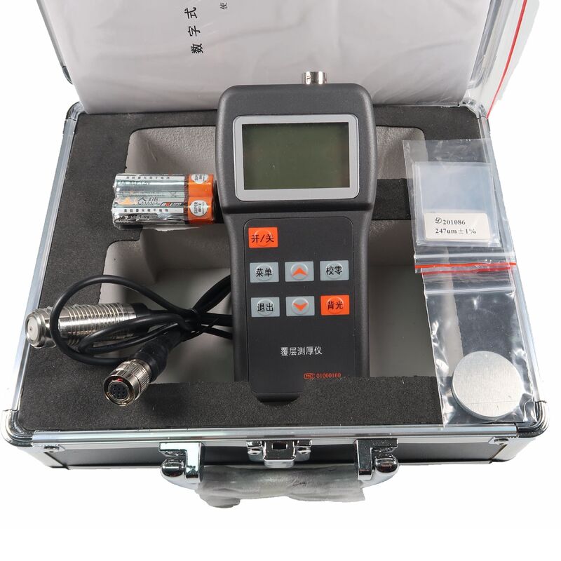
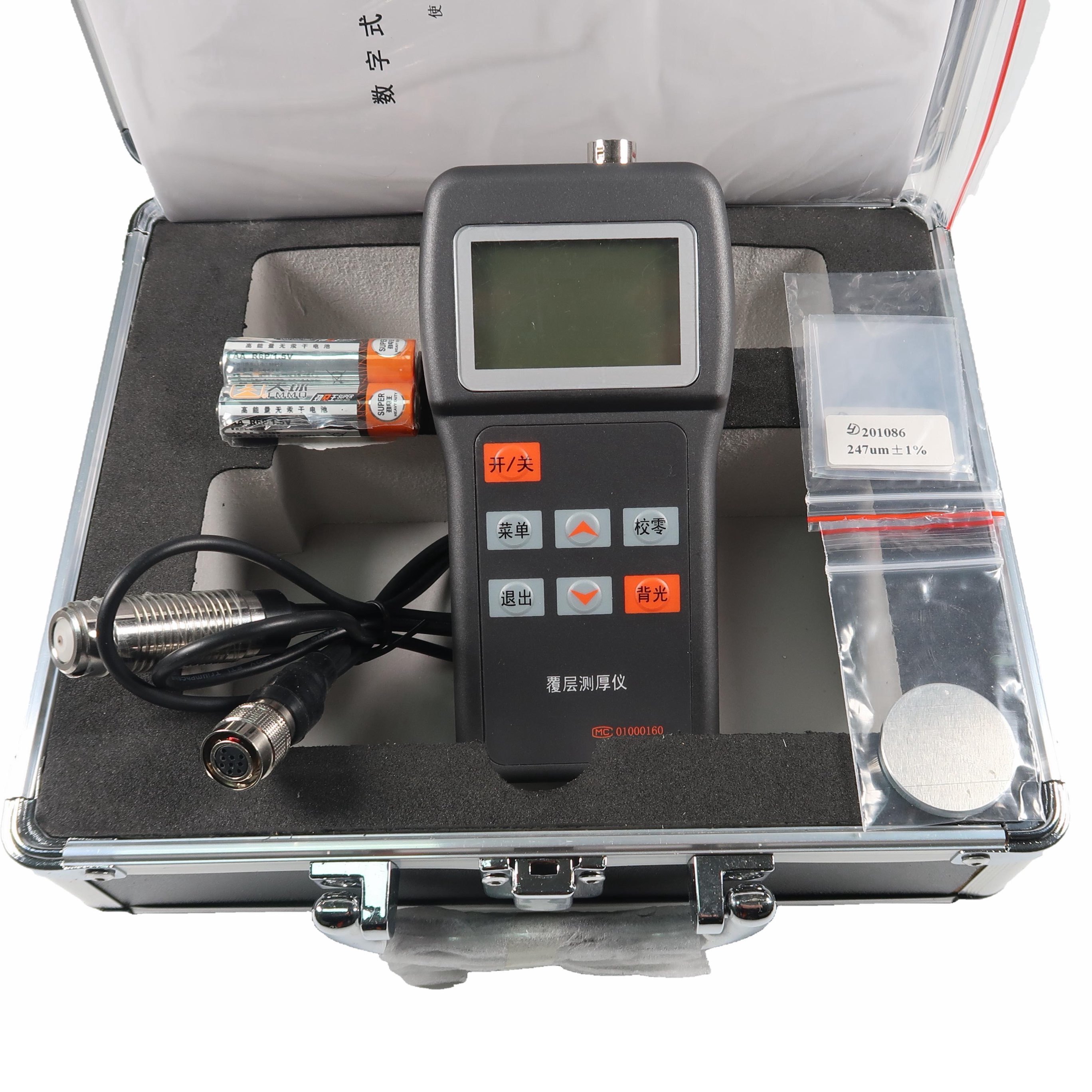
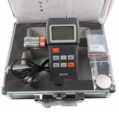
| Main unit | 1 |
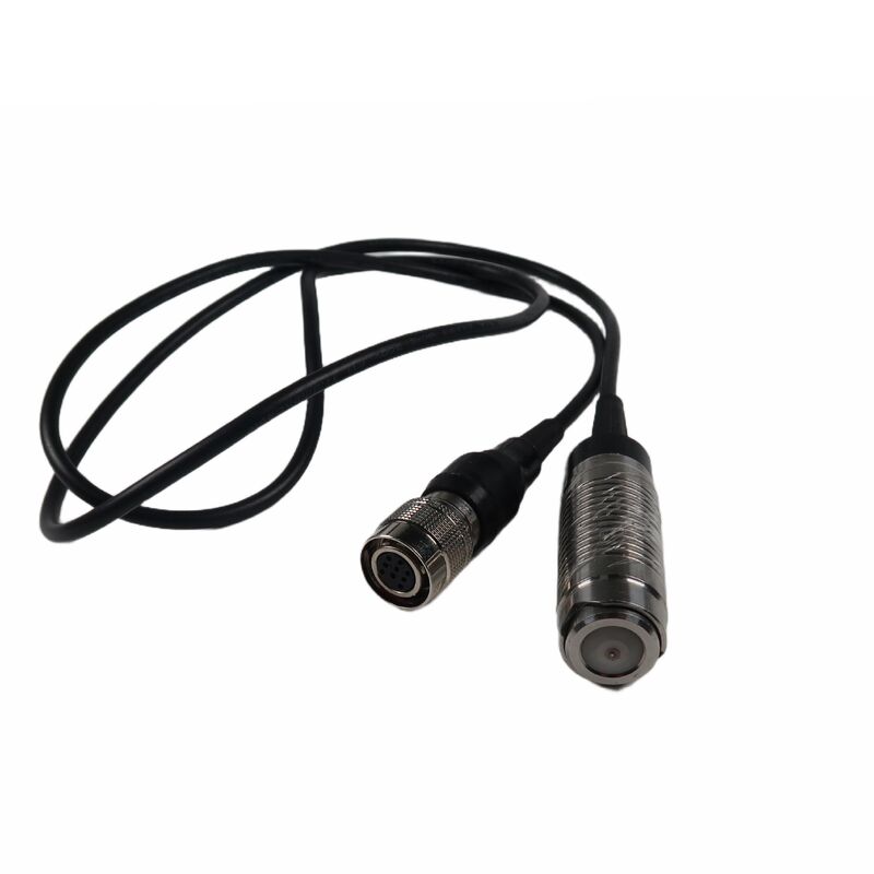
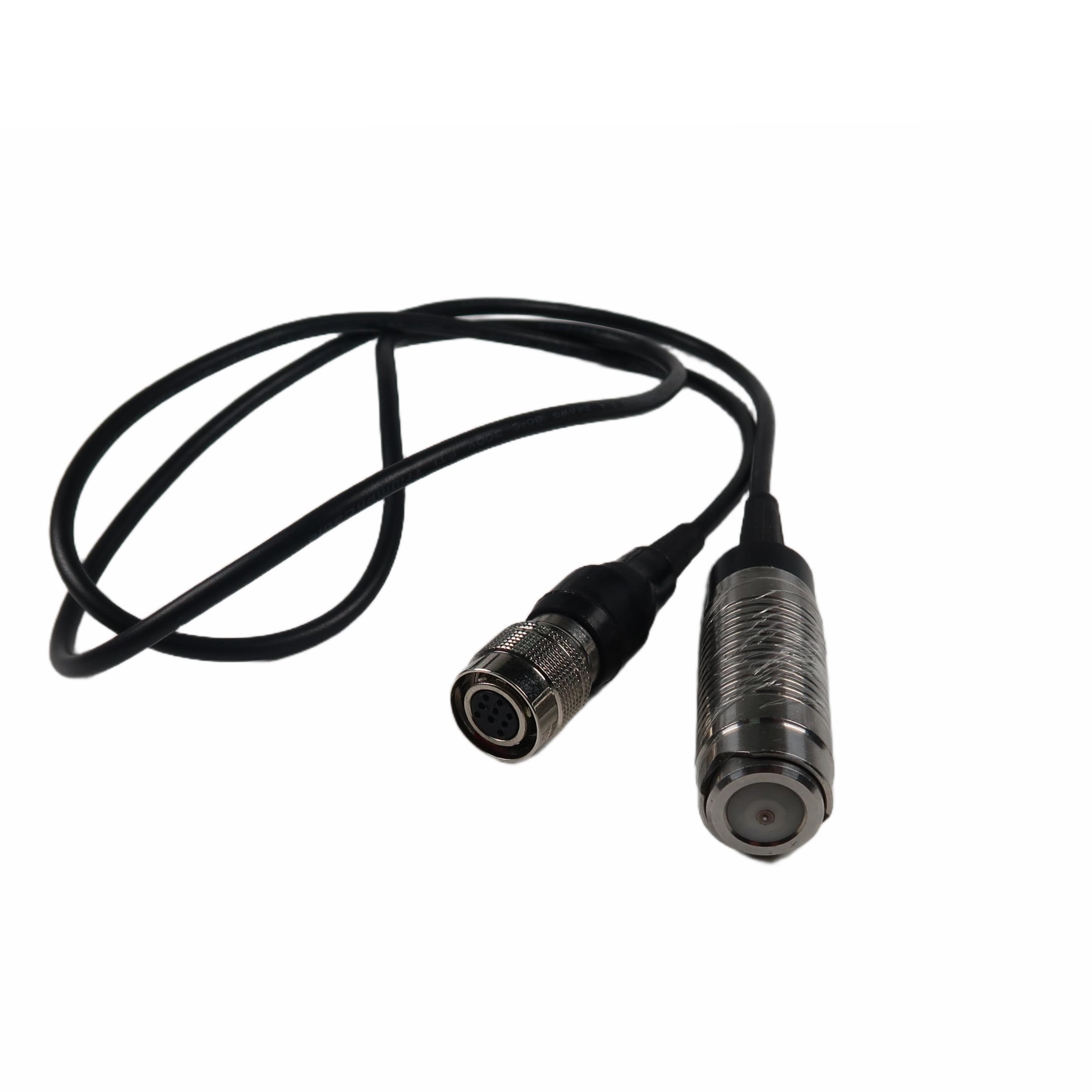
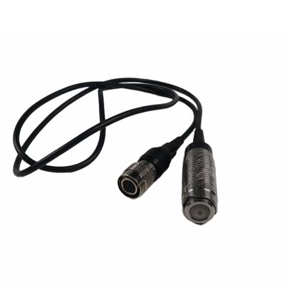
| Probe F300 for high-temperature testing | 1 |
| Calibration foils | 5 |
| Instruction manual | 1 |
| Certificate | 1 |
| Warranty card | 1 |
| Carrying case | 1 |
| Communication cable | 1 |
| PC software DataView | 1 |
| Probe | F400 | F1 | F1/90° | F5 | F10 |
|---|---|---|---|---|---|
| Measuring principle | Magnetic method | ||||
| Measuring range (mm) | 0–400 µm | 0–1250 µm | 0–5000 µm | 0–10000 µm | 0–10000 µm |
| Min. resolution (mm) | 0.1 | 0.1 | 1 | 10 | 10 |
| Tolerance — one-point calibration (mm) | ±(2%H + 0.7) | ±(2%H + 1) | ±(3%H + 5) | ±(2%H + 10) | ±(2%H + 10) |
| Tolerance — two-point calibration (mm) | ±(1%H + 0.7) | ±(1%H + 1) | ±(1–3%H + 5) | ±(1%H + 10) | ±(1%H + 10) |
| Min. radius of curvature, convex (mm) | 1 | 1.5 | Flat | 5 | 10 |
| Min. measuring area (mm) | F3 | F7 | F7 | F20 | F40 |
| Min. thickness of base material (mm) | 0.2 | 0.5 | 0.5 | 1 | 2 |
| Probe | N400 | N1 | CN02 |
|---|---|---|---|
| Measuring principle | Eddy current method | ||
| Measuring range (mm) | 0–400 µm | 0–1250 µm | 10–200 µm |
| Min. resolution (mm) | 0.1 | 0.1 | 1 |
| Tolerance — one-point calibration (mm) | ±(2%H + 0.7) | ±(2%H + 1.5) | ±(2%H + 1) |
| Tolerance — two-point calibration (mm) | ±(1%H + 0.7) | ±(1%H + 1.5) | — |
| Min. radius of curvature, convex (mm) | 1.5 | 3 | Flat |
| Min. measuring area (mm) | F4 | F5 | F7 |
| Min. thickness of base material (mm) | 0.3 | 0.3 | 0 |
Note: H = measured value.